Ir Sensor Circuit Diagram Using 555 Ir (infrared) Detector C
Diy ir sensor module circuit diagram 555 timer tester circuits ne555 electronicshub optocoupler Ir sensor circuit diagram with arduino
555 Timer IC - Electronic Circuits and Diagrams-Electronic Projects and
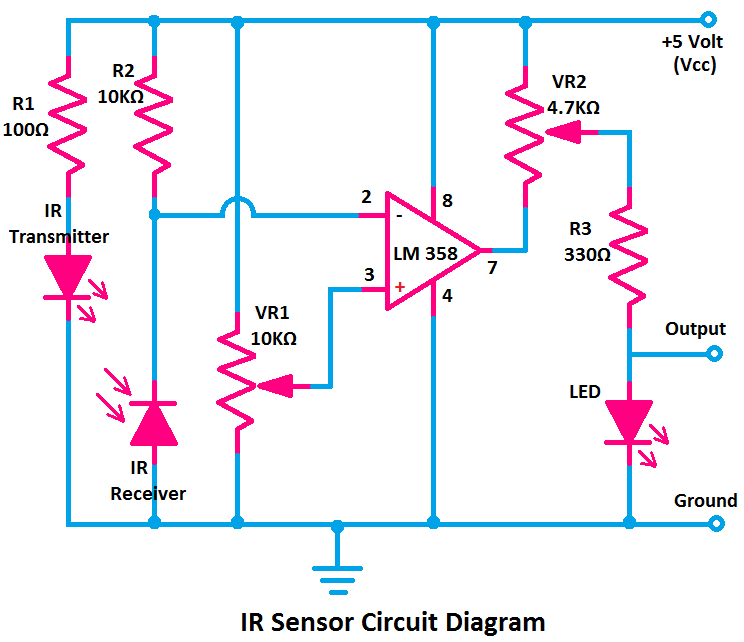
Timer 555 circuit schematic electronic circuits control ic relay using simple charger schematics board diagrams timing multivibrator battery basic choose Ir sensor circuit diagram using lm358 Sensor ir circuit led proximity diagram infrared photodiode module work object electronic lm358 pair 9v motion using circuits electrical ic
What is an ir sensor : circuit diagram & its working
Ir sensor array circuit diagramCircuit diagram of ir sensor using 555 timer Ir sensor circuit, connection diagram, project11+ optocoupler tester circuit diagram.
Ir sensor module circuit diagramOperational amplifier Ir sensor monitor circuit diagram ( infrared )Ir infrared sensor with arduino.
Make a 555 ir motion detector proximity sensor emitter circuit
Circuit ir 555 detector ic diagram timer using buzzer sensor wiring infrared led circuits electronic baseProximity sensor detector Ir sensor with nodemcuInfrared remote control for home appliances.
Circuit belowIr sensor circuit, connection diagram, project Receiver ir circuit tsop1738 555 infrared ic using gadgetronicx diagram timer circuits ic555 article audio arduino amplifierPulsed ir sensor.

Pin on electrical, electronics
Circuit diagram of 555 timerIr (infrared) detector circuit diagram using 555 timer ic Ir sensor interfacing with microcontroller (mikro c)Ir sensor circuit diagram.
Ir sensor module circuitSensor interfacing microcontroller mikro infrared 555 timer ic workingCircuit diagram of ir sensor using 555 timer.

Sensor connection
555 timer ic diagram ne555 lm555 projects circuits electronic invention camenzind hans story historyCircuit ir sensor diagram line simple robot following rx tx Ir infrared receiver circuit using ic 555 tsop1738 – artofit1 ic led flashing circuit using 555 timer.
Arduino ir sensor circuit diagramTimp liber siglă uşor mouse ir sensor pinout inspirație g omis Sensor sensors circuits infrared using arduino receiver detector microcontroller elprocus detect emitterIr receiver 38khz circuit circuits infrared 38 schematic diagram pulsed module emitter problem article sensor board gr next constructed prototyping.

Simple line following robot: simple ir sensor circuit
Ir sensor circuit and working with applications electronic circuit555 timer ic Ir transmitter tsop1738 remote control circuit diagram using range led infrared appliancesDiy ir sensor module circuit diagram.
Timer 555 schematic555 timer ic Ir led transmitter and receiver circuit.


555 TIMER IC working - circuit diagram, waveforms and working Of 555

1 IC LED Flashing Circuit Using 555 Timer

IR (Infrared) Detector Circuit Diagram using 555 Timer IC

Ir Sensor Circuit Diagram Using Lm358 - Circuit Diagram

timp liber siglă uşor mouse ir sensor pinout Inspirație G Omis

Circuit Diagram of IR Sensor using 555 Timer - The Engineering Projects

Circuit Diagram of IR Sensor using 555 Timer - The Engineering Projects